I was playing with datasets and wanted to share with what beautiful visualizations but wrong map alignment looks like.

The different colors represent scans but merged improperly (not aligned).


Looks like a mess.

But overall the coloring is important with debugging what this data represents.
Here’s what it looks like all merged together properly.

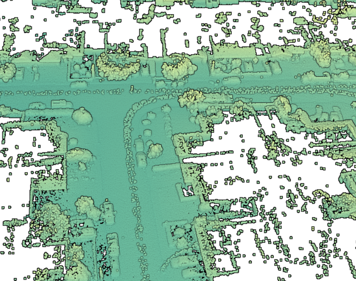
Especially the truck


Lidar map merging is a difficult task, and merging the data takes quite some time. So it is better to sample parts of a large data set and see if the algorithm is doing the right job.


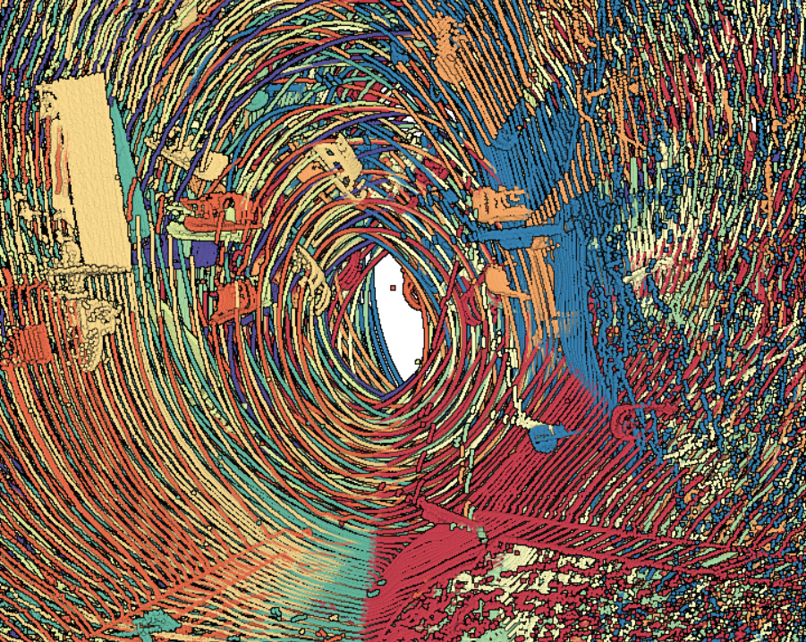
At least the lidar above were all in the same 2D plane.
Here’s what it looks like if they weren’t — a blob of mess.

double pitch = rtkMessage.pitch();
double yaw = – rtkMessage.heading();


double pitch = deg2rad(rtkMessage.pitch());
double yaw = deg2rad(rtkMessage.heading());

double pitch = deg2rad(rtkMessage.pitch());
double yaw = – deg2rad(rtkMessage.heading());

I tried a bunch of different methods and it turns out that I was using degrees in place of radians.
Here’s what after 5 days of working on this problem I finally solved


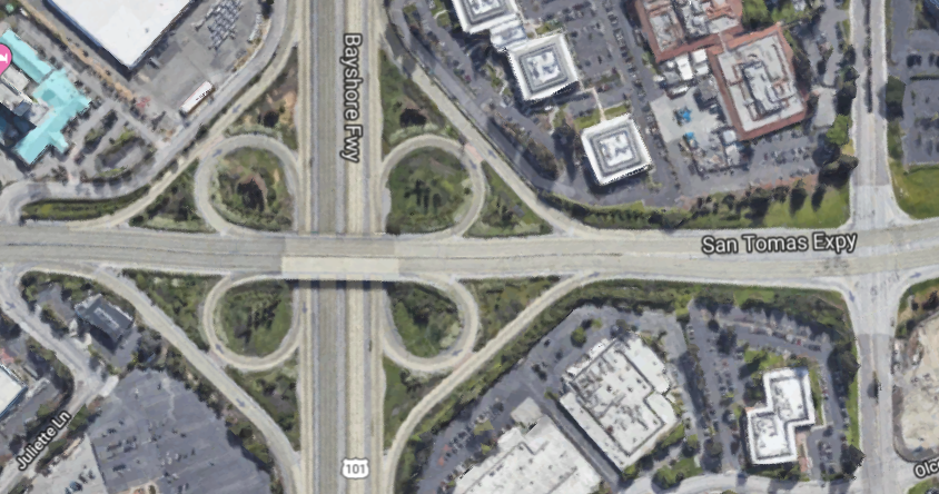
Here’s what the Google Maps view looks like
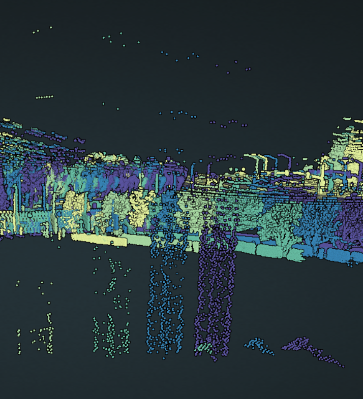
And here’s what the lidar point cloud data only looks like

Different view


Construction crane can be seen here.


Very interesting in the map stitch process!